Luiz Fernando dos Santos Pereira - chaos@linux.ime.usp.br
Advisor and revision: V. W. Setzer - www.ime.usp.br/~vwsetzer
Version 1.0 - March 30, 2004
This manual describes how to use the ASIN plugin for the IBM Eclipse environment. This plugin implements the parser generator described in [1, 2], introducing an additional feature: a non-terminal symbol may have another non-terminal as its alternative.. The highlights of the parsing method are:
1. Accepts a class of LL(1), called ESLL(1) grammars (for "Extended
Simple LL(1) grammars), written with extended right-hand sides, such
transitive closures, options, etc.
2. The grammar may be drawn as a syntax graph, thus facilitating its
design, testing and correction.
3. From the grammar, the parsing method automatically generates syntax
error messages and produces automatic error recoveries using 4
different strategies, notifying the user what kind of recovery was made.
4. Semantic routines may be called after recognition of any syntax
symbol.
5. The parse stack is available to semantic routines for eliminating
superfluous elements that have been stacked.
The parser uses the JFlex lexical analyzer, providing a standard scanner, which can be modified by the user to suit his lexical needs. Guidelines are given permitting the user to implement his own semantic routines, that is, context analysis and code generation routines.
The parsing method has many advantages over LALR(1) methods, such as the widely used YACC and Bison systems, such as items 1-5 above. Its only drawback is not accepting left recursions.
This manual supplies the user with enough information for using the ASIN plugin as a tool to implement his syntax-oriented compiler or interpreter. It describes: 1. How to install the plugin in Eclipse Platform; 2. How to make a grammar description by editing a text file or using a syntax graph in graphical form. 3. How to parse a source file, according to a given grammar. This manual has the following topics:
1. InstallationWe begin with the description of this input format, because it is also automatically generated as an intermediate file when using the graphical input format. Thus, it helps understanding the graphical format, but it is not an essential step for using the latter, which is much simpler and safer to use.
To create a grammar description in text form, open your favorite text editor, for example Emacs or Vi in Unix-like systems and WordPad or NotePad in Windows, or even better, use the Eclipse text editor.
A text description is actually a table with six columns, each row representing one grammar symbol. A symbol can be a left side of a production, a Terminal or a Non-Terminal Symbol, or a Lambda-Alternative. From left to right the columns are the following.
Type: indicates if the symbol is a Terminal (T), Non-Terminal (N) or a Left Side - header - (H) of a production.
Name: contains the symbol name
written with any characters, except the space character.
Number: contains the symbol
number within the symbols of that header.
AlternativeNode: contains a
symbol number for the symbol which is the successor to the present
symbol.
SuccessorNode: contains a
symbol number for the symbol which is the alternative to the present
symbol.
SemanticRoutine: contains a
semantic routine number, which will be called after this symbol is
recognized during a parse phase.
For example.: Suppose we want to create the text input for the following grammar:
S -> a(b | Sc) | dM | e
M -> {fS}*
The full text format describing this grammar could be:
H S 0
-1 -1 -1
T a 1 5
2 -1
T b 2
3 0 -1
N S 3
0 4 -1
T c 4
0 0 -1
T d 5
7 6 -1
N M 6
0 0 -1
T e 7
0 0 -1
H M 0 -1
-1 -1
T f 1
3 2 -1
N S 2
0 1 -1
T -1 3
0 0 -1
The first line is the header symbol (a non-terminal consisting of the left side of a production) S, its number has to be 0. The seven following lines correspond to the right-side of the production for S. For example line 2 of this production corresponds to the terminal a, witch begins the production for S. This line also informs that the symbol a has an alternative one (c), which is in line 5 of this production, and a successor symbol (b), which is in line 2 of this production. Line 3 represents a non-terminal S without an alternative symbol (0) and a successor symbol (c) at line 4. Line 9 of the table is the header for the production of M, which consists of the remaining lines. In line 12 there is a lambda-alternative, indicated by -1 in the Name column, with no successor and no alternative, necessary to terminate the transitive closure *.
The graphical input permits the user to draw and edit a syntax graph providing for a simple visual representation of a grammar, and eliminating the burdensome task of giving the correct alternative and successor symbol numbers necessary for the grammar text input. A syntax graph can be used to generate a text input as described above.
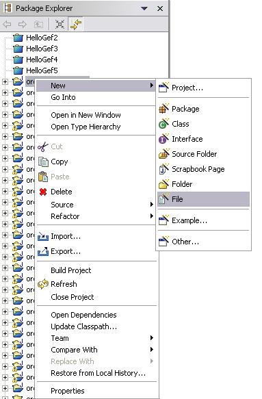
The first action for using the graphical tool is to create a file for saving the syntax graph which represents the desired grammar. For this, click the right mouse button on the view Navigator or on the view PackageExplorer and select New -> File, as shown in the next figure.
Fig. 2.2-1 Open a new file
Enter the name for the file, with extension .asin ; this name just has to follow the operating system rules, for instance test.asin.
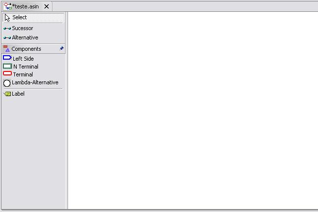
Once the file is created, the graphic editor is activated. The editor's toolbar and workspace are shown below.
A syntax graph consists of a set of connected subgraphs, each one representing a grammar production. The figure below shows a syntax graph for the grammar given in the previous section; the nodes were labeled node i just for an easy reference in the text.
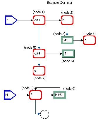
Fig. 2.2.1-1 Graph elements
This graph consists of two subgraphs, for the productions of S and M. The types of graphical elements are:
a) Components
 |
Represents the left side non-terminal of a production, called the left side node. Examples at fig.2.2.1-1: the pentagon nodes for S and M. |
 |
Represents a non-terminal symbol node. Examples: the rectangles for S and M. |
 |
Represents a terminal symbol node. Examples: the rounded rectangles for a and b. |
 |
Represents a lambda-alternative node. Example: to bottommost node. The lambda-alternative can also be represented as a terminal-node with "-1" as its name, without alternative. The latter representation must be used if the user wants associate a semantic routine to the lambda-alternative node. |
By default, nodes with "-1" as its name are lambda-nodes i.e. nodes representing the empty-string.
If the user wants to activate a semantic routine just after a node corresponding to a grammar symbol has been recognized, he may type the semantic routine number after the node name using a # as a separator, e.g. d#4 in fig. 2.2.1-1.
The grammar symbol represented by a node is its name, edited in a name box. Each node, except the lambda-node must have a name.
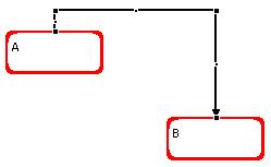
b) Connectors
 |
Represents a successor connector, drawn with a solid, black line. The arrow points to the (only) successor node of the node where it starts at. Example: the connector between nodes a and b. |
 |
Represents an alternative connector, drawn with a blue line. The arrow points to the (only) alternative node of the node where it starts. Example: the connector between a and d. |
Texts may be inserted anywhere in the workspace, and are used for titles and comments. The only distinction between a text and a node name is that the latter becomes a part of the node. Example: in fig. 2.2.1-1, the texts Syntax graph for the example grammar, node 3, etc.
The toolbar to the left of the workspace contains 4 sections. The first one activates a cursor to select a part of the graph. The second one contains the different connectors used to link two nodes of the graph or to link a semantic routine to a node. The third one contains graph components, which are node elements and the box to associate a semantic routine to a node, and the last one activates a feature to write text titles and comments on the graph.
To use one of these tools click with the left button on it, then click with the left button on the workspace to insert the element into it.
Following the restrictions of the parser, only one successor and one alternative connector can be drawn for a source node. At its present stage of development, the system does not verify if the user draws more than one successor and one alternative connectors for a given source node, but it only considers as in effect the last one of each that was drawn.
To draw a connector between two nodes, click on one of the connectors at the tool bar, then on a component, which will be considered the source node. Move the mouse cursor to another node, and click again the left button on a node that will be the target node. See section 2.2.7 "connector patterns" for further details.
The function of each tool is:
 Used to connect two nodes indicating that the target node will be the
successor of the source node.
Used to connect two nodes indicating that the target node will be the
successor of the source node.
 Used to connect two nodes indicating that the target node will be the
alternative of the source node.
Used to connect two nodes indicating that the target node will be the
alternative of the source node.
 Used to create the left side of a production. This node can be a
source node of just a successor connector and it can never be a target
node. Any violation to this rule will be rejected by the program. The
node is created with the default name: "Left Side", this name can be
changed late
Used to create the left side of a production. This node can be a
source node of just a successor connector and it can never be a target
node. Any violation to this rule will be rejected by the program. The
node is created with the default name: "Left Side", this name can be
changed late
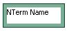
 Used to create a non-terminal node. Default name inserted into the
node: N Terminal.
Used to create a non-terminal node. Default name inserted into the
node: N Terminal.
 Used to create a terminal node. Default name: Terminal.
 Used to create a lambda-alternative node.
 This tool permits the user to define a place in the workspace
where he may enter a single line with any text (used for titles and
comments).
This tool permits the user to define a place in the workspace
where he may enter a single line with any text (used for titles and
comments).
There are two types of context menus: the workspace and the node context menus. The first one is selected when the mouse right button is activated on an empty workspace area and displays the following:
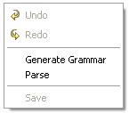
Fig. 2.2.3-1 Context menu
The first two options may be used to undo the actions made on the workspace as well as to redo these actions. The option Generate Grammar generates the text format for the grammar. Selecting this option, the user will be required to choose a directory and name for the text file. There are no restrictions for this file name its file extension.
The Parse option requires the specification of a source file containing a string to be parsed by the grammar defined by the text format, and activates the parse. It will be described later on in this manual.
The Save option saves the graphic description of the current syntax graph. The shortcut Ctrl+S or the menu options File -> Save and File -> Save as ... work as well for this purpose.
Clicking on the name of a named component (such a terminal node), displays the following expanded context menu:
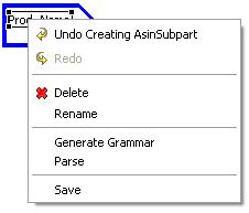
The options common to the working space context menu are the same.
Click on Rename to edit a node name or to change a text.
These operations require a selection of a node or group of nodes. To select a node, left-click in its area. To select a group, left-click on any position in the workspace, maintain the mouse button pressed, and drag the mouse pointer to the desired opposite rectangle corner, encompassing various nodes. The next figure shows how a group is selected. A selected node appears within rectangles with 8 small squares, used to change its sizes in the usual graphic software way.
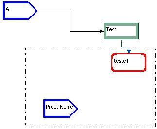
Fig. 2.2.6-1 Grouping nodes
Another way is to hold the Ctrl key and
click with the left mouse button on consecutive nodes. Once the group
is selected, the objects can be dragged or resized. To resize click the
left button on one of the eight square marks on the object border
and drag the mouse up to the desired size. When the mouse is inside the
marks the mouse pointer will change its shape to  .
.
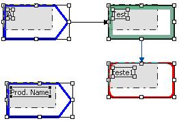
Fig. 2.2.6-2: Resizing nodes
In the above picture the action is decreasing the size of all the nodes simultaneously, because they were previously selected forming a group.
To move a node or group of nodes click with the left button inside a component, except on a square mark, or within the area of a group, and drag the mouse.
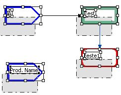
Fig. 2.2.6-3 Moving nodes
The above figure shows the action of moving all the nodes simultaneously.
A more accurate way of moving objects is also provided. For this, select only one component then punch the keyboard arrows to move the selected object one space unit. Pressing simultaneously the Shift or Ctrl key and an arrow key moves the object 1/2 or 1/4 space unit, respectively.
The GEF Eclipse plug-in provides two connector patterns: the Manhattan pattern, which uses only vertical and horizontal lines with right angles on bend points, and the manual pattern, which permits the user to move the bend points producing line segments of any inclination, and any bend angles. The kind of pattern can be changed at any time, producing immediately a change of connector shapes that can be changed. For instance, an exception to this rule is a horizontal connector linking two nodes which are at the same horizontal level in the graph: in both patterns, the connectors are the same.
The only thing that can be changed in the Manhattan pattern is an anchor point. Each node has 4 anchor points. To change the anchor point of a connector, select the latter by clicking the mouse left button on it. The end points of the connector are shown with small squares; click on one of them, maintain the left mouse button pressed and drag it to another possible anchor point in the same another node. If the left button is released inside a node but away from a possible anchor point, the closest one is used.
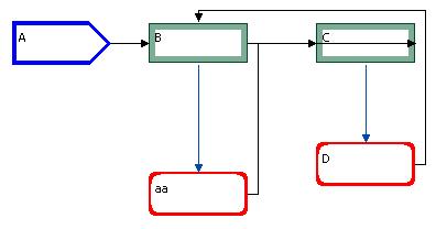
This pattern only works well for small grammars. When the grammar becomes more complex, this it may produce unsatisfactory results. An example is displayed below.
|
Fig. 2.2.7-1 Manhatam |
Fig. 2.2.7-2: Overlapping Manhatam |
Note that both graphs represent the same grammar. When the anchor point of the successor connector in node aa (drawn to the bottom at the left figure just for this example) is moved to the right side of the node, the Manhattan pattern produces a line segment overlapping node C.
To change from Manhattan to manual pattern and vice-versa, click with the left button on the workspace, then in the Eclipse platform view menu Properties, then click again with the left button in the text box selecting the desired pattern, as shown below.
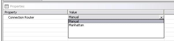
Fig. 2.2.7-3: Connector Patterns
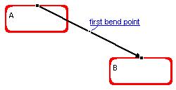
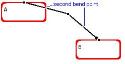
In the manual pattern the user may select a connector in the same way as in the other pattern. This produces the appearance of a bend point, a small black square right in the middle of the connector, defining two segments of the same size. Clicking on a bend point and moving it changes the direction and (equal) sizes of its two segments, and produces the appearance of two additional bend points, one in each of the two segments adjacent to the original bend point, thus defining 4 new segments. This gives the possibility of producing connectors with arbitrary any number of line segments. Moving a bend point so that its two adjacent segments become a straight line segment, eliminates its two neighboring bend points. For example:
|
Fig. 2.2.7-4 |
In
this picture the user clicked on the connection; a bend point appeared in the middle of the link. |
|
Fig. 2.2.7-5 |
The user clicked
on the first bend point; as soon as he started dragging it up, two new bend points appeared in the connection. |
|
Fig. 2.2.7-6 |
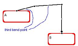
Dragging
the top second bend point produces two new bend points; they are captioned as "third bend point" |
|
Fig. 2.2.7-7 |
Finally,
selecting the second bend point on the left and dragging it, the connection achieves the desired shape. |
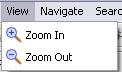
This plugin supplies a tool for zooming-in and zooming-out the syntax graph. There are two ways of accomplishing this task. The first is located in the tool bar:

Fig. 2.2.8-1
|
Fig. 2.2.8-2 |
Here the user is choosing the percentage of the zoom. |
|
Fig. 2.2.8-3 |
Another way is by
using the menu options View -> Zoom-in or View-> Zoom-out |
Fig. 2.2.9-1 Outline View
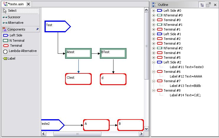
Fig. 2.2.9-2 Elements list
The nodes created by the user are displayed in the outline view to help the user to locate them. If the user clicks on a node listed at the right pane, the workspace screen automatically selects this node and sets it on focus.
The second resource is:
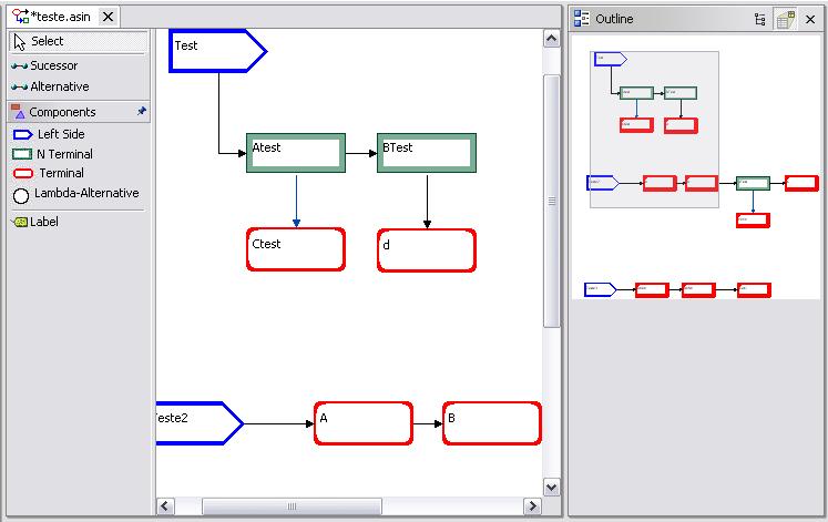
Fig. 2.2.9-3 Browser graph
This resource helps the user to navigate on the graph. The outline view displays a zoomed-out copy of the graph. A gray box is shown and may be moved around the outline graph. Selecting with it a group of nodes makes the workspace window show the corresponding nodes.
To produce a parse for a given source file according to a certain grammar, the user may activate the parsing routine at any time. For this, click the right button in the Workspace and select the Parse option.
Fig. 2.4-1 Parse option
The following window is shown:
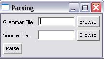
Fig. 2.4-2: Parse window
The top field must be an address of a file containing a grammar in text format and the bottom field must be the name of a file with the source to be parsed. The Parse button starts the parse.
The grammar file must follow the rules described in the section "Text format" or having been generated by a syntax graph. The plugin output will be displayed as an ASIN output view. The next section describes how to open this view. The output is specified in the description of the parse method.
The following optional items may be displayed as results of processing the plugin: the table of terminal symbols constructed from the grammar, the source file lines, each lexical item recognized by the lexical analyzer, the syntax stack, the semantic stack, syntax errors, the performed error recovery strategy. Furthermore, the plugin may be used to interpret the source file or to compile it generating a translation into some language. In both cases, the user may specify that he wants to see the results obtained by the semantic routines, that is, the output specified by the interpreted code or the generated object code, respectively. These various output items are displayed in the ASIN Output View. The user should open this view manually in the following path: Window -> Show View -> Other... -> ASIN -> ASIN Output View.
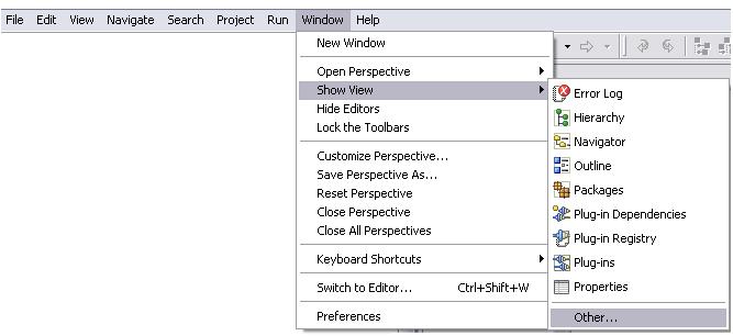
Fig. 3-1 Open plugin output
After clicking in Other...:
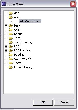
Fig. 3-2
Then select ASIN Output View and click OK. With this procedure this view will be displayed on the Eclipse Platform
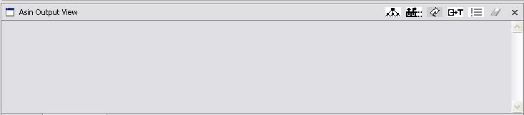
Fig. 3-3
The Output View buttons are used to display on the Output View the following:
 Syntax stack
 Semantic stack
 Output produced by semantic
routines
Output produced by semantic
routines
 Last token recognized by the
lexical analyzer
Last token recognized by the
lexical analyzer
 Error recovery strategies that did
not succeded
Error recovery strategies that did
not succeded
![]() Clear the Output
View
Clear the Output
View
The syntax stack is displayed in the following way. If it has n symbols, only the topmost elements, from (n/10)*10+1 up to (n/10)*10 + n mod 10 are displayed, where / indicates integer division. For example, if there are 23 symbols in the stack, only symbols 21, 22 and 23 are displayed, preceded by 21 as a reference.
To modify the lexical analyzer and to program semantic routines, the user has to open the plugin directory org.eclipse.gef.asin_2.1.1. There, the compressed file asin.jar contains all the source codes and the Java bytecodes of this plugin. The user must extract the lexical analyzer or semantic routines files of asin.jar, modify and compile the files and then update the asin.jar with the new files. Some examples are shown below.
If the user types in the operating system prompt jar xf asin.jar the whole source code and the bytecode will be extracted to the current directory. The lexical analyzer and semantic routines files are in the directory
currentdirectory\org\eclipse\gef\asindesigner\model\analisador\
where currentdirectory is the directory in use.
The lexical analyzer and semantic routines files contain comments to facilitate the understanding of the user. There is also an indication on which functions and variables should not be changed or removed for the adequate functioning of the plugin.
This plugin uses the JFlex to generate the scanner. The Jflex and its user's manual are available on http://jflex.de . We programmed a default scanner whose code is on file Scanner.jflex. A copy of this file is in the directory org.eclipse.gef.asin_2.1.1.
After creating or editing a JFlex file, the user must activate JFlex to generate the Yylex.java code which will perform the lexical analysis. For this, run jflex xxx.flex, where xxx is the name of the created or edited .flex file. The plugin requires that JFlex return a Yytoken object far each recognized lexical token. The Yytoken class is declared in the file Yytoken.java.
To extract the Yytoken.java issue the prompt command
jar asin.jar org\eclipse\gef\asindesigner\model\analisador\Yytoken.java
To compile the modified Yylex.java plugin source file, issue
javac -classpath asin.jar Yylex.java
To compile the Yytoken, issue
javac -classpath asin.jar Yytoken.java
In the two last command lines above, the system supposes that the asin.jar or its copy is in the same directory as Yylex.java and Yytoken.java. Otherwise, the user must type the path of the asin.java. For example, if asin.jar is in the directory \MyDir\Jar, the compile line should be
javac -classpath \MyDir\Jar\asin.jar Yylex.java
Now the Yylex.java and Yylex.class files must be updated:
jar -uf asin.jar org\eclipse\gef\asindesigner\model\analisador\Yylex.java
jar -uf asin.jar org\eclipse\gef\asindesigner\model\analisador\Yylex.class
To update the Yytoken.java and Yytoken.class files issue
jar -uf asin.jar org\eclipse\gef\asindesigner\model\analisador\Yytoken.java
jar -uf asin.jar org\eclipse\gef\asindesigner\model\analisador\Yytoken.class
A nice tutorial about .jar files and the Java compiler javac is on http://java.sun.com/docs/books/tutorial/jar/basics.
After all this, if the updated asin.jar is not in the directory org.eclipse.gef.asin_2.1.1, the user must copy the former to this directory and restart the eclipse platform.
Semantic routines are declared in SemanticRoutines.java. By editing this file the user may create. change or remove semantic routines. If the user wants to use ASIN to implement an interpreter instead of a compiler, this plugin offers the Semantic Routine Output View to display on the screen results produced by semantic routines. For this it is necessary to compile SemanticRoutines.java with the jar file workbench.jar, located in the plugin directory org.eclipse.ui.workbench_xxx where xxx is the version of the workbench plugin. A copy of workbench.jar is also available on directory org.eclipse.gef.asin_2.1.1/extLibs, containing its version 2.1.1.
As in the previous section, firstly we need to extract SemanticRoutine.java:
jar asin.jar org\eclipse\gef\asindesigner\model\analisador\SemanticRoutine.java
After programming the semantic routines on SemanticRoutine.java the user must compile it:
javac -classpath asin.jar;workbench.jar SemanticRoutines.java
with the Semantic Routine Output View or
javac -classpath asin.jar SemanticRoutines.java
without that view.
The last step is updating the asin.jar, so the created or changed routines be available to the plugin:
jar -uf asin.jar org\eclipse\gef\asindesigner\model\analisador\SemanticRoutines.java
jar -uf asin.jar org\eclipse\gef\asindesigner\model\analisador\SemanticRoutines.class
After that if the updated asin.jar is not in the directory org.eclipse.gef.asin_2.1.1, the user must copy the updated asin.jar to this directory and restart the eclipse platform.
Before the parser analyzes the source file, it creates an object of the class SemanticRoutine. This object encapsulates the semantic routines defined by the user. When a terminal or a non-terminal node is recognized during the parse, the syntax analyzer calls the semantic routine associated to that node. For example, in the grammar of fig. 2.2.1-1, when the parse recognize a terminal d, it calls the SemanticRoutine object, which calls semantic routine 4.
The core of the functioning of semantic routines is the semantic stack. This stack runs parallel to the syntax stack whose name in the plugin is parseStack, of Java's standard class Stack (for its description, see section stack class at http://java.sun.com/j2se/1.4.2/docs/api/). Each of its cells is an object of type parseStackCell. Each cell is composed of two fields: the syntax symbol parseStackCell.syn and its corresponding semantic object parseStackCell.sem. Whenever a non-terminal grammar symbol is recognized and the syntax stack is popped-up, the semantic stack is also popped-up. Semantic routines have access to the semantic stack cells and the top of both stacks. The topmost symbol the semantic stack can be examined with parseStack.peek().sem(). To change its value, use the parseStackCell method sem(Object). Semantic routines may pop-up both stacks, for instance when some topmost syntax stack symbols are not going to be used anymore; a common case is that of parsing a list of variable declarations of a programming language, and the list is recognized as a whole (a non-terminal) - after having defined the parameters of a declared variable, it may be erased from the stack because it has no influence on the following variables.
When the SemanticRoutines object is created, the parse passes the parse stack and the token table (TabT) to the latter. When a token is recognized, the parse sends to SemanticRoutines a Yytoken object containing the recognized token and useful information about as its value and type. For example, if the token is an identifier, its text value and its type as specified in the identifier table are passed. Thus the user has a complete environment information to write the semantic routines. The user has full access to the semantic stack and the symbols table thus the semantic routines may alter those elements.
Further information is available on SemanticRoutine.java.
If the user wishes to display the result of some semantic routines, such as the results of an interpreter, or he wants to see the code generated by the compiler he is building, he must call the function OutputView.displayText(string) in the semantic routine code. For example, the the function rs2 of the SemanticRoutines.java, may be:
private void rs2(){SemanticView.displayText("rs2: Text: "+currentToken.m_text+" Type:"+currentToken.m_p1+"\n");}
this routine prints in the ASIN Output View the token recognized by the lexical analyzer and its type.
In this strategy the parse supposes the user wrote the source string with a superfluous extra symbol. For example, suppose the string in the source file is a a d f g e c c . This string is not generated by the example grammar, but the string a a d f e c c is. So this routine eliminates the g, issues an error message and the recovery action taken, and continues with the parsing. If the input string is a a d f g g g e c c, this strategy eliminates the g g g. The outputs at the ASIN Output View are:
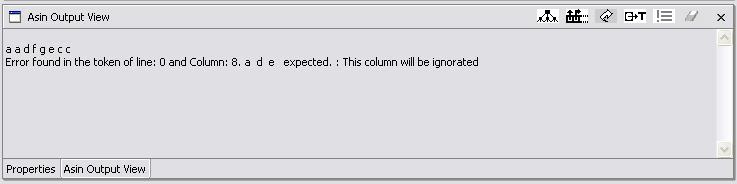
Fig. 5.1-1 First example of error message and elimination strategy
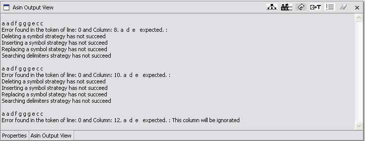
Fig. 5.1-2 Second example of error message
In fig. 5.1-2 we see messages indicating which error recovery strategies have not succeeded. These messages were displayed because the corresponding icon was activated. Note the order in which the strategies are tested.
In this strategy the parser supposes the user has omitted a symbol just after the last symbol which was recognized, and before the symbol which produced the error. For example, the string d f b is not generated by the example grammar, but the string d f a b is. Then the parse inserts the symbol a in the string, notifies the user and continues with the parsing:
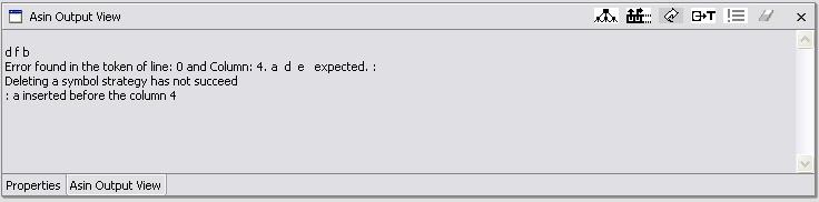
Note that in this case the symbol elimination strategy has not worked.
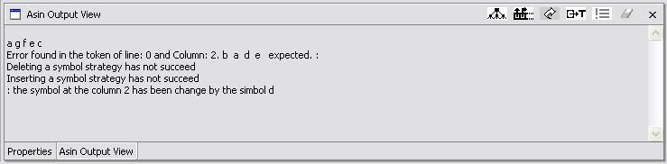
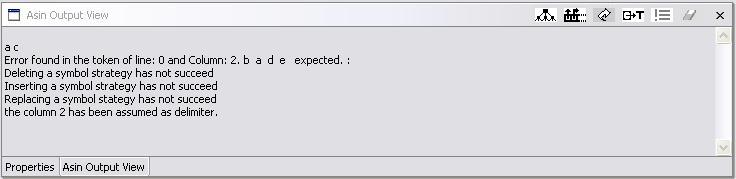
In the example grammar the recognition of non-terminal node 3 (S) is necessarily followed by the recognition of node 4 (c). Thus, node 4 is considered as a delimiter to whatever is generated by the S at node 3; if an error occurs during the recognition of the S at node 3, and the other strategies do not work, the parser looks for one of its delimiters; founding a c, it considers S as having been recognized, and continues with that c at node 4. For example, the input string a c is not in the example grammar; this strategy assumes c as the delimiter to node 3, forcing the parser to recognize the non-terminal (S) at at this and then recognizes the input symbol c at node 4:
This section shows how to use this plugin to construct an interpreter for a grammar generating arithmetic expressions with unary minus and plus, addition, subtraction, multiplication, division and parentheses. The interpreter performs the calculations, thus it works as a simple calculator.
The calculator syntax graph is:
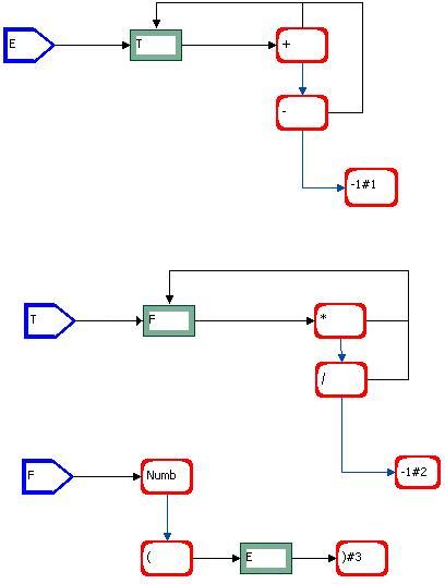
Fig. 6.1
Recall that, at the present stage of the plugin, whenever the user wishes to draw a lambda-alternative calling a semantic routine, he must draw a terminal node with name -1 (cf. 2.2.1). The semantic routines to interpret the input string and display the result is shown in table 6.1. They were incorporated into the plugin file SemanticRoutines.java ; this way the user has an example of semantic routines, and may just replace them by his own ones. Section 4.2 describes how to do this.
| /* * Created on 12/03/2004 * * To change the template for this generated file go to * Window>Preferences>Java>Code Generation>Code and Comments */ package org.eclipse.gef.asindesigner.model.analisador; import java.util.Stack; import org.eclipse.gef.asinview.AsinView; public class SemanticRoutines { /*The user may add variables of any type.*/ private Stack parseStack; //This variable is the parse Stack. **Should not be removed.** private TabNode TabT[];//This variable is the table of reserved symbols. **Should not be removed.** private Yytoken currentToken;//This variable contains the last recognized token **Should not be removed.** /*The constructor of this class*/ public SemanticRoutines(Stack parseS,TabNode tbT[]) { parseStack = parseS; TabT = tbT; } /*The parse calls this method when it recognizes a token. Thus the variable currentToken contains the last * recognized token*/ public void setCurrentToken(Yytoken cToken) { currentToken = cToken; } /*The method below switches to the semantic routine to executed. In this default file, there are only 3 * semantic routines; if the user wants to add more routines, he should add them here, e.g.: * case 5: * this.rs5(); * break; * ... **/ public void execFunction(int r) { switch (r) { /*the value -1 indicates the node without semantic routine*/ case -1 : //AsinView.semanticRoutinesOutput("The recognized node has not semantic routine\n"); break; case 1 : this.rs1(); break; case 2 : this.rs2(); break; case 3 : this.rs3(); break; default : } } /*Here begin the codes for the semantic routines. If the user wants to add a semantic routine, he should create a method for it, e.g.: * private void rs5(){....}. * The name and return value of this method must be coherent with the method execFunction above.*/ private void rs1() { ParseStackNode aux; int index = this.parseStack.size()-1;//top int acumulator; aux = (ParseStackNode)this.parseStack.elementAt(index); acumulator = aux.intSem(); index--; while(index > 0){ aux = (ParseStackNode)this.parseStack.elementAt(index); if(aux.syn().equals("+")){ index--; aux = (ParseStackNode)this.parseStack.elementAt(index); acumulator = acumulator + aux.intSem(); index--; } else if(aux.syn().equals("-")){ index--; aux = (ParseStackNode)this.parseStack.elementAt(index); acumulator = aux.intSem() - acumulator; index--; }else{ break; } } /* Stores the final result assigned to the non-terminal T into the first parse and semantic stack cell of T; * this way, the semantic stack will show the partial and final results. */ ((ParseStackNode)this.parseStack.elementAt(++index)).sem(acumulator+""); if(index <= 0){ AsinView.semanticRoutinesOutput("Result: "+acumulator+"\n"); } } private void rs2() { ParseStackNode aux; int index = this.parseStack.size()-1;//top int acumulator; aux = (ParseStackNode)this.parseStack.elementAt(index); acumulator = aux.intSem(); index--; while(index >= 0){ aux = (ParseStackNode)this.parseStack.elementAt(index); if(aux.syn().equals("*")){ index--; aux = (ParseStackNode)this.parseStack.elementAt(index); acumulator = acumulator * aux.intSem(); index--; } else if(aux.syn().equals("/")){ index--; aux = (ParseStackNode)this.parseStack.elementAt(index); acumulator = aux.intSem() / acumulator; index--; }else{ break; } } /* Stores the final result assigned to the non-terminal T into the first parse and semantic stack cell of T; * this way, the semantic stack will show the partial and final results. */ ((ParseStackNode)this.parseStack.elementAt(++index)).sem(acumulator+""); } private void rs3() { Object aux; int index = this.parseStack.size()-1;//top aux = ((ParseStackNode)this.parseStack.elementAt(index-1)).sem(); ((ParseStackNode)this.parseStack.elementAt(index-2)).sem(aux); } } |
Table 6.1
Basically, the user should only implement the methods rs1(), rs2() and rs3().
After following the steps in section 2.3 the file of Table 6.2 will be generated.
| H E -1 -1
-1 -1 N T 1 0 2 -1 T + 2 3 1 -1 T - 3 4 1 -1 T -1 4 0 0 1 H T -1 -1 -1 -1 N F 1 0 2 -1 T * 2 3 1 -1 T / 3 4 1 -1 T -1 4 0 0 2 H F -1 -1 -1 -1 T Numb 1 2 0 -1 T ( 2 0 3 -1 N E 3 0 4 -1 T ) 4 0 0 3 |
Table 6.2
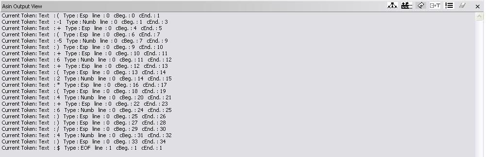
If the user follows the steps of the section 2.4 for the source file with the input below,
(-1 + (-5) + 6 + (2 * (4+6)) / 4)
the various output windows will be the following; for simplification, we have separated each category of output.
Semantic routines output:
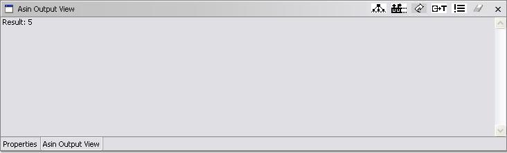
Fig. 6.2
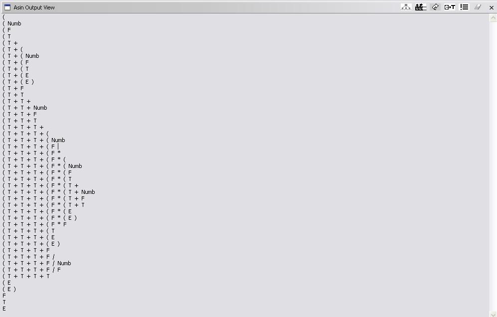
Parse stack:
Semantic stack:
Fig. 6.4
Recognized tokens:
[1] Setzer, V.W. and Melo, I.S.H.M. A Construção de um Compilador (The construction of a compiler). Rio de Janeiro, Ed. Campus, 1989.
[2] Setzer, V.W. and Mayer, R. Simple Syntax Graphs and their Parse with Error Recovery. Technical Report RT-MAC-9005, Dept. of Computer Science, Institute of Mathematics and Statistics, University of São Paulo, Brazil.